27 March 2012

week 9


27 MARCH 2012

After attending Arduino workshop last week, I tried to do simple buzzer program. This buzzer is planned to be insert in my timer. The purpose is, after certain time, for example, 2 minutes, the buzzer will sound. I set it 2 minutes time is just for demo on the presentation day. For real application, I will set the buzzer to sound after 8 hours. It is to alert user to switch off the supply and rest the motor for few hours before start use it again. The existing ripple mattress doesn’t have this function. What makes it cross my mind to add these features is, in real world, nurses at hospitals or users often forget to switch off the supply. This could damage the motor; and reduce its lifetime if use in 24 hours continuously.

First of all, I construct simple buzzer circuit
    - Connect a wire (blue wire in photo below) from pin 4 to the breadboard.
         - Connect the other side of the wire to the 100R resistor.
        - Connect the 100R resistor to the buzzer.
        - Connect the buzzer to the other (yellow in photo) wire.
       - Connect the wire to the GND pin on the Arduino. 

     so, in order to start programming using Arduino software, we have to install the software in our laptop. Just follow the installation instruction by clicking “Next” until “Finish”.  Then, follow this simple instruction: 

     1)  Check Arduino ports at our Control Panel. Click System.


     2)  In System Properties, click Hardware, then Device Manager
  

    3)  In Device Manager, see under Ports (COM & LPT). Make sure the ports to      be set in the Arduino are the same as appear in Device Manager. for example, in the device manager shows COM19,same as in Arduino.


    Don't forget to set Arduino Uno board (refer to the board that you use) in Tools. 


    Here, i provide the example of 2 minutes program. To test the program, we have to compile it by click upload symbol à
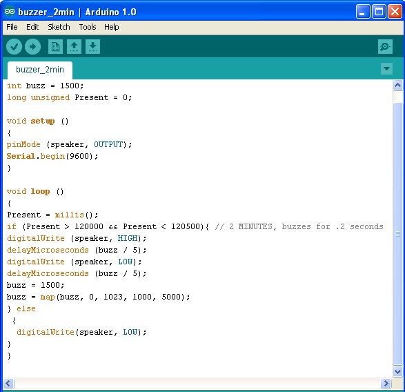
  
     Here is the result:


19 March 2012

ARDUINO WORKSHOP BY SIR ZUL


18 MARCH 2012


This weekend, Medical Section committee conducted Arduino workshop. It is open for any course, but targeted especially for FYP student. There is lots of things that we get from this workshop as it is conducted for the beginners ; from Introduction to Arduio, how to install the software, run simple program such as running LED and switches, be guided line-by-line and the important command that should have in the programming and many more.  
we also being provided with CD that consists of Arduino e-book, example of program, power point notes, support program such as Fritzing and Toolduino software.  


Here is some interesting point that can be highlighted through out these workshop:

ABOUT ARDUINO:

Arduino is great because it can give you results right away, and quickly build your confidence and understanding. Confidence is the only real currency of innovation after all. Once you have that, you can move on to more sophisticated projects. But without an easy-to-understand entry point, you’ll never get there at all.


  •       It's an open-source physical computing platform based on a simple micro-controller board, and a development environment for writing software for the board.
  •       Arduino projects can be stand-alone, or they can be communicate with software running on your computer (e.g. Flash, Processing, Max MSP.)

  •       The boards can be assembled by hand or purchased pre-assembled; the open-source IDE can be downloaded for free. 
SPECIFICATIONS OF ARDUINO:
  •        Microcontroller: ATmega328
  •        Operating Voltage: 5V
  •        Input Voltage (recommended): 7-12V
  •        Input Voltage (limits): 6-20V
  •        Digital I/O Pins: 14 (of which 6 provide PWM output)
  •        Analog Input Pins: 6
  •        DC Current per I/O Pin: 40 mA
  •        DC Current for 3.3V Pin: 50 mA
  •        Flash Memory: 32 KB (ATmega328) of which 0.5 KB used by bootloader
  •        SRAM: 2 KB (ATmega328)
  •        EEPROM: 1 KB (ATmega328)
  •        Clock Speed: 16 MHz
Runs on: Windows, Mac OS X, Linux
Languages: Wiring/Arduino, C/C++
Getting Started guides: Clear step-by-step instructions, from download to blinking LED.
Knowledge base:
• Many simple examples included with download
• Good reference guide to the commands
• Large knowledge base on Arduino site and elsewhere
Advantage:
• Can be run as I/O board, using Firmata firmware
• Very large knowledge base
• Simple language, but expandable using C/C++
• Multiple models, for shields, breadboards, wearable, extra I/O pins
• Many shield modules
• Large number of open source derivative boards
Disadvantage:
• C language constructs (semicolons, brackets, case sensitivity) are confusing

:: Arduino also can be stand alone. it is impossible for FYP student to attach Arduino board in their project. so, to make it stand alone, it just requires two capacitors, and oscillator; connected Atmega 328P and 5V supply. 


NOTE: I can try applying Aduino in my project to add function such as alarm if the tube disconnect from the mattress, or add LCD display; for example, to display amount of pressure delivered into or sucked out of the mattress.    

12 March 2012

week 8


 12 march 2012


As i have mention before, i think stepper has the best characteristic to be use in my project. so, i learn more about stepper this week. Stepper has many types. we have to choose it based on number of step that it produce. 


First of all, I simply choose a stepper with 50 number of step. There are six wires emerging from the stepper motor: two red, two yellow, and two grey. We will call the wires R1, Y1, G1, R2, Y2, and G2 where the letter is the first letter of the wire's color and the number is to differentiate them. The next step is, measuring the resistance to determine the connection. Systematically we connected the testing leads of the multimeter to pairs of wires coming out from the stepper motors and put the measured results into the following simple table:


R1
R2
G1
G2
Y1
Y2
R1

-
117
-
117
-
R2
-

-
117
-
117
G1
117
-

-
234
-
G2
-
117
-

-
236
Y1
117
-
234
-

-
Y2
-
117
-
234
-

    All of the above results are measurements taken in Ohms. Infinite resistance is represented by a '-'. 

Where the resistance between two wires is infinite we know there is no connection between those two wires within the stepper motor. For example, between R1 and R2 or G1 and G2. We have two different values of resistance between the other wires - 117 Ohms and 234 Ohms with one being half of the other. This is because this stepper motor has four phases and therefore four identical coils. When the resistance measured between two wires is 117 Ohms, the wires are connected across one coil, and when the resistance is 234 Ohms the wires are connected across two coils.

R1 is connected to G1 and Y1 across one coil. R2 is connected to G2 and Y2 across one coil. G1 and Y1 are connected across two coils, and G2 and Y2 are connected across two coils. None of the 2's are connected to any of the 1's. Therefore we can draw the following simple diagram of the wiring of this stepper motor:
Stepper Motor Wiring Diagram

The four live wires are G1, G2, Y1, and Y2, and there are two common wires R1 and R2


Here i attached some picture as for reference:
.


Now, I know how to connect stepper motor and do simple programming to test it. =) 


2 March 2012

week 7


1st of March


Nothing much i can do this week as it is a phase tests week. 


I didn't have much time to have a discussion with Mdm. Naza as the time is quite limited. But i do meet her in a short period to discuss about using two motor; based on Sir Zubir suggestion. So, one is for pumping air and the other for sucking. 


Mdm Naza advise me to do more research regarding the motor.Yes, it is not efficient to use two motor just for pumping and sucking the air. I need to research more about this. 


Next week will be mid-term break.. I plan to come back earlier to complete my project. but then, all Medical Section staff are not around for the entire week. =(
So, i'll proceed with my research regarding selection of pump and motor.