22 April 2012

week 14


22 APRIL 2012


Finally, it’s week 14. I’m getting very busy this week as everything needs to be settled. It’s time to design a poster, prepare casing for my pump, final troubleshoot and testing overall function. I also need to prepare video; just in case my project not functioning on the presentation day.

CASING FOR THE PUMP:


 POSTER:


Almost forgot, I need to think how I’m going to demonstrate my mattress. It is very impossible for me to bring the single bed mattress to the hall. So, I’m thinking of just demo it using balloons. The balloon is just to show assessor the principle operation of the mattress. By using the balloons, it is clearer to show division of air between two tubes; that emerge from the pump (this will create alternating flow to the mattress).

DEMO FOR MATTRESS:

1st try, FAILED.!
2nd try
Success..!

:: I hope the demonstration goes well and I can answer every question given by the assessor (Sir Azmi Hashim from electrical section and Mdm Afifah from Medical Section).

VIDEO:


20 April 2012

week 13


20 APRIL 2012


It is week 13..!!! After doing etching for standalone Arduino and alarm timer for my circuit, it’s time for testing. First of all, I check the connection and continuity using multimeter. Unfortunately, I found that there is much connection broken. So, I refer with Miss Siti; technician level 1 electric lab. She suggest to re-do again the PCB DipTrace layout, by “bold” the connection line; as the line is too thin. Time is running out, and I need to go to Jalan Pasar again, to buy new UV board. After repeating the etching process, I test the connection and continuity again; thank god it is well connected..! =)

Broken Connection

It’s time for inserting and solders the component to the PCB. As I’m not doing this soldering work for a long period, it is a bit smudgy… but, I manage to finish it in few hours and start testing. It is not functioning… I try to troubleshoot it by re-check the connection. But, still the same. One of my friend suggested to use different battery or replace the battery by adapter; because it might be not functioning because of not enough supply, as the battery power reduce each time we use it. After try all the suggestion, it is still not functioning. So, I try to compare the circuit with the one in the internet. Referring to the circuit, I jump wire emerge from voltage regulator (5V), direct to pin number 7 Atmega. What a release, it is functioning.. =)


Lastly, it’s time for uploading full programming in the Atmega and testing overall function.  


15 April 2012

week 12


15 APRIL 2012


It’s time to itching on PCB. At first, I plan to itching manually, using PCB iron paper and normal PCB board. But, it is difficult as I don’t have experience doing it by myself and need to learn the process from the expert. I’m also afraid of doing mistake that could burn my money; as the iron paper is costly. Finally, I decided to itching on UV board, as it is easier and I can do it at level 1; PCB lab. I can use the facilities and it is for free. =)

  1.               Photocopy the PCB layout  in OHP sheet using laser printer   

 2.  Attach the OHP sheet on the UV PCB board. Put a tape at each side to attach the paper to the board. Precaution: Avoid the board from exposure to light.


           3. Place board with OHP sheet into a UV exposure unit for 60 second.


    4.  Wash the developing using ferric chloride. Sink the PCB in the acid and shake it until the circuit clear  from copper; which do not need on a board.


5.   Transfer the PCB in to itching tank and do the operation for 4 minutes; 40˚C onward.


6. After finish on itching tank, scrub the PCB board using sand paper or rub it using thinner liquid. Make sure there is a right connection and continuity on the PCB. Test it using multimeter.


For the first try, after checking the connection and continuity, i found that there is no connection at some point. It is because of my connection line too thin. So, I have to adjust my connection line again; in the DipTrace software, and repeat overall procedure. Here is the result:


8 April 2012

week 11


8 APRIL 2012

This week, i start focusing on PCB layout for stand alone Arduino (for timer display and alarm). 
I choose to design my layout in DipTrace software. At first, it is hard to start, as i'm not familiar with this software. But, in few hours time, i know where to find the component, draw the connection and make my own component hole for the component those i can't find. It takes almost four hours for me to complete the layout; but i'm proud because i manage to do it myself. =)
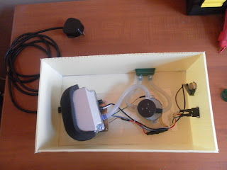
Here, i attach the complete layout:


This layout consists of: 
- Atmega 328
- LED
- Resistors
- Crystal Oscillator
- Capacitor
- Voltage Regulator
- Push button switch
- Buzzer
- LCD


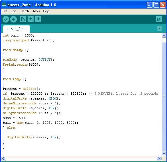
Besides doing this layout, this week, i'm also focusing on the Arduino timer program. I have tried few program, But it is hard to find like i want. Finally, i found this one program and after some modification, i manage to run a timer. =)
Below is the simple process:


Parts List :
1) 1x 16×2 parallel LCD display (compatible with Hitachi HD44780 driver)
2) 1x Arduino
3) 1x 10kΩ potentiometer
4) 1x 10kΩ resistor
5) 1x switch
6) Jumper wire

Instruction :
1) Connect all jumper wire as shown in diagram.


2) Connect digital input from switch to digital pin 2.

3) Upload this code to your Arduino


#include <LiquidCrystal.h> 

LiquidCrystal lcd(7, 8, 9, 10, 11, 12);
 
int ledPin = 13;                    // LED connected to digital pin 13
int buttonPin = 2;                  // button on pin 2
 
int value = LOW;                    // previous value of the LED
int buttonState;                    // variable to store button state
int lastButtonState;                // variable to store last button state
int blinking;                       // condition for blinking - timer is timing
int frameRate = 100;                // the frame rate (frames per second) at which the stopwatch runs - Change to suit
long interval = (1000/frameRate);   // blink interval
long previousMillis = 0;            // variable to store last time LED was updated
long startTime ;                    // start time for stop watch
long elapsedTime ;                  // elapsed time for stop watch
int fractional;                     // variable used to store fractional part of Frames
int fractionalSecs;                 // variable used to store fractional part of Seconds
int fractionalMins;                 // variable used to store fractional part of Minutes
int elapsedFrames;                  // elapsed frames for stop watch
int elapsedSeconds;                 // elapsed seconds for stop watch
int elapsedMinutes;                 // elapsed Minutes for stop watch
char buf[10];                       // string buffer for itoa function
 
void setup()
{
  lcd.begin(16, 2);                // intialise the LCD.
  pinMode(ledPin, OUTPUT);         // sets the digital pin as output
  pinMode(buttonPin, INPUT);       // not really necessary, pins default to INPUT anyway
  digitalWrite(buttonPin, HIGH);   // turn on pullup resistors. Wire button so that press shorts pin to ground.
}
 
void loop(){
  digitalWrite(ledPin, LOW);            // Initiate LED and Step Pin States
 
  buttonState = digitalRead(buttonPin); // Check for button press, read the button state and store
 
// check for a high to low transition if true then found a new button press while clock is not running - start the clock    
   if (buttonState == LOW && lastButtonState == HIGH  &&  blinking == false){
    startTime = millis();                               // store the start time
      blinking = true;                                  // turn on blinking while timing
      delay(10);                                         // short delay to debounce switch
      lastButtonState = buttonState;                    // store buttonState in lastButtonState, to compare next time 
   }
 
// check for a high to low transition if true then found a new button press while clock is running - stop the clock and report
   else if (buttonState == LOW && lastButtonState == HIGH && blinking == true){
   blinking = false;                                    // turn off blinking, all done timing
   lastButtonState = buttonState;                       // store buttonState in lastButtonState, to compare next time
 
// Routine to report elapsed time            
   elapsedTime =   millis() - startTime;                // store elapsed time
   elapsedMinutes = (elapsedTime / 60000L);
   elapsedSeconds = (elapsedTime / 1000L);              // divide by 1000 to convert to seconds - then cast to an int to print
   elapsedFrames = (elapsedTime / interval);            // divide by 100 to convert to 1/100 of a second - then cast to an int to print
   fractional = (int)(elapsedFrames % frameRate);       // use modulo operator to get fractional part of 100 Seconds
   fractionalSecs = (int)(elapsedSeconds % 60L);        // use modulo operator to get fractional part of 60 Seconds
   fractionalMins = (int)(elapsedMinutes % 60L);        // use modulo operator to get fractional part of 60 Minutes
   lcd.clear();                                         // clear the LDC
 
 if (fractionalMins < 10){                            // pad in leading zeros
      lcd.print("0");                                 // add a zero
      }
 
    lcd.print(itoa(fractionalMins, buf, 10));       // convert the int to a string and print a fractional part of 60 Minutes to the LCD
      lcd.print(":");                                 //print a colan. 
 
 if (fractionalSecs < 10){                            // pad in leading zeros
      lcd.print("0");                                 // add a zero
      }
 
 lcd.print(itoa(fractionalSecs, buf, 10));          // convert the int to a string and print a fractional part of 60 Seconds to the LCD
   lcd.print(":");                                    //print a colan. 
 
 if (fractional < 10){                                // pad in leading zeros 
      lcd.print("0");                                 // add a zero
      }     
 
 lcd.print(itoa(fractional, buf, 10));              // convert the int to a string and print a fractional part of 25 Frames to the LCD
   }
 
 else{
      lastButtonState = buttonState;                  // store buttonState in lastButtonState, to compare next time
   }
 
// run commands at the specified time interval
// blink routine - blink the LED while timing
// check to see if it's time to blink the LED; that is, the difference
// between the current time and last time we blinked the LED is larger than
// the interval at which we want to blink the LED.
 
 if ( (millis() - previousMillis > interval) ) {
 
    if (blinking == true){
       previousMillis = millis();                    // remember the last time we blinked the LED
 
       digitalWrite(ledPin, HIGH);                   // Pulse the LED for Visual Feedback
 
       elapsedTime =   millis() - startTime;         // store elapsed time
         elapsedMinutes = (elapsedTime / 60000L);      // divide by 60000 to convert to minutes - then cast to an int to print
         elapsedSeconds = (elapsedTime / 1000L);       // divide by 1000 to convert to seconds - then cast to an int to print
         elapsedFrames = (elapsedTime / interval);     // divide by 40 to convert to 1/25 of a second - then cast to an int to print
         fractional = (int)(elapsedFrames % frameRate);// use modulo operator to get fractional part of 25 Frames
         fractionalSecs = (int)(elapsedSeconds % 60L); // use modulo operator to get fractional part of 60 Seconds
         fractionalMins = (int)(elapsedMinutes % 60L); // use modulo operator to get fractional part of 60 Minutes
         lcd.clear();                                  // clear the LDC
 
       if (fractionalMins < 10){                     // pad in leading zeros
         lcd.print("0");                             // add a zero
         }
 
       lcd.print(itoa(fractionalMins, buf, 10));   // convert the int to a string and print a fractional part of 60 Minutes to the LCD
         lcd.print(":");                             //print a colan. 
 
       if (fractionalSecs < 10){                     // pad in leading zeros 
         lcd.print("0");                             // add a zero
         }
 
       lcd.print(itoa(fractionalSecs, buf, 10));   // convert the int to a string and print a fractional part of 60 Seconds to the LCD
         lcd.print(":");                             //print a colan. 
 
       if (fractional < 10){                         // pad in leading zeros 
         lcd.print("0");                             // add a zero
         }
          lcd.print(itoa((fractional), buf, 10));  // convert the int to a string and print a fractional part of 25 Frames to the LCD
         }
 
    else{
          digitalWrite(ledPin, LOW);            // turn off LED when not blinking 
          }
 }
 
}

:: Its works, and this is the result:


3 April 2012

Synchronous motor


A synchronous electric motor is an AC motor in which the rotation rate of the shaft is synchronized with the frequency of the AC supply current; the rotation period is exactly equal to an integral number of AC cycles. Synchronous motors contain electromagnets on the stator of the motor that create a magnetic field which rotates in time with the oscillations of the line current. The rotor turns in step with this field, at the same rate.

The speed of the synchronous motor is determined by the number of magnetic poles and the line frequency. Synchronous motors are available in sub-fractional self-excited sizes to high-horsepower direct-current excited industrial sizes.

Advantage of synchronous motor:

  • Speed is independent of the load, provided an adequate field current is applied.
  • Accurate control in speed and position using open loop controls, e.g. stepper motors.
  • They will hold their position when a DC current is applied to both the stator and the rotor winding.
  • Their power factor can be adjusted to unity by using a proper field current relative to the load. Also, a "capacitance" power factor, (current phase leads voltage phase), can be obtained by increasing this current slightly, which can help achieve a better power factor correction for the whole installation.
  • Their construction allows for increased electrical efficiency when a low speed is required (as in ball mills and similar apparatus).
  • They run either at the synchronous speed or they do not run at all.


Outline drawing


Specification:


Features:


1. Miniature in size but delivers high torque. 
2. Low noise and smooth revolution.
3. Motor rotation: freely. It can be CW or CCW. If need it to turn just in one direction, can add a
directional plate. In this case, the motor rotation would be irreversible.
4) Long life (more than 8,000 hours), low noise [less than 40dB (A)], low temperature rising (less than 60K), and high torque.


2 April 2012

week 10


2 APRIL 2012


It’s time for me to focus on the motor and pump. For the guideline, first of all, I plan again my block diagram. Here is my block diagram:


This project requires motor and pump for the main operation.  So, from the block diagram, when power supply is switch on, it will activate air pump which will suck air from environment and delivered it to the valve. Air pump is controlled by pressure controller. I’m using variable resistor 50K to control the pressure of air pump. When variable resistor is turn to the maximum, it will give high pressure of air through the valve, to the mattress and vice verse.

Valve; which the rotation is controlled by motor will delivered the air through two tubes to the mattress. Here come the difficulties for me to choose the best motor to rotate the valve. These valves have three chambers; which one of it is from the air pump, and another two I connect to the mattress by tube.  When the motor rotate, it wills also rotating the valve. So, each time only one chamber to the mattress will open to deliver air to the mattress. The other chamber will not delivered air. After half cycle, the other chamber opens to delivered air, and vice versa. This will generate alternating flow to the mattress.

Valve: after half cycle each valve will open to delivered air

Three chamber valve. 1 from air pump; the other 2 to the mattress

Finally, I decided not to use Stepper motor, and choose synchronous brush less DC motor to rotate the valve. It is because, the operation of both motor is similar; but stepper requires programming for it to operate; which requires more time to explore and troubleshoot. Later I’ll explain the specification of the synchronous motor. =)

27 March 2012

week 9


27 MARCH 2012

After attending Arduino workshop last week, I tried to do simple buzzer program. This buzzer is planned to be insert in my timer. The purpose is, after certain time, for example, 2 minutes, the buzzer will sound. I set it 2 minutes time is just for demo on the presentation day. For real application, I will set the buzzer to sound after 8 hours. It is to alert user to switch off the supply and rest the motor for few hours before start use it again. The existing ripple mattress doesn’t have this function. What makes it cross my mind to add these features is, in real world, nurses at hospitals or users often forget to switch off the supply. This could damage the motor; and reduce its lifetime if use in 24 hours continuously.

First of all, I construct simple buzzer circuit
    - Connect a wire (blue wire in photo below) from pin 4 to the breadboard.
         - Connect the other side of the wire to the 100R resistor.
        - Connect the 100R resistor to the buzzer.
        - Connect the buzzer to the other (yellow in photo) wire.
       - Connect the wire to the GND pin on the Arduino. 

     so, in order to start programming using Arduino software, we have to install the software in our laptop. Just follow the installation instruction by clicking “Next” until “Finish”.  Then, follow this simple instruction: 

     1)  Check Arduino ports at our Control Panel. Click System.


     2)  In System Properties, click Hardware, then Device Manager
  

    3)  In Device Manager, see under Ports (COM & LPT). Make sure the ports to      be set in the Arduino are the same as appear in Device Manager. for example, in the device manager shows COM19,same as in Arduino.


    Don't forget to set Arduino Uno board (refer to the board that you use) in Tools. 


    Here, i provide the example of 2 minutes program. To test the program, we have to compile it by click upload symbol à

  
     Here is the result:


19 March 2012

ARDUINO WORKSHOP BY SIR ZUL


18 MARCH 2012


This weekend, Medical Section committee conducted Arduino workshop. It is open for any course, but targeted especially for FYP student. There is lots of things that we get from this workshop as it is conducted for the beginners ; from Introduction to Arduio, how to install the software, run simple program such as running LED and switches, be guided line-by-line and the important command that should have in the programming and many more.  
we also being provided with CD that consists of Arduino e-book, example of program, power point notes, support program such as Fritzing and Toolduino software.  


Here is some interesting point that can be highlighted through out these workshop:

ABOUT ARDUINO:

Arduino is great because it can give you results right away, and quickly build your confidence and understanding. Confidence is the only real currency of innovation after all. Once you have that, you can move on to more sophisticated projects. But without an easy-to-understand entry point, you’ll never get there at all.


  •       It's an open-source physical computing platform based on a simple micro-controller board, and a development environment for writing software for the board.
  •       Arduino projects can be stand-alone, or they can be communicate with software running on your computer (e.g. Flash, Processing, Max MSP.)

  •       The boards can be assembled by hand or purchased pre-assembled; the open-source IDE can be downloaded for free. 
SPECIFICATIONS OF ARDUINO:
  •        Microcontroller: ATmega328
  •        Operating Voltage: 5V
  •        Input Voltage (recommended): 7-12V
  •        Input Voltage (limits): 6-20V
  •        Digital I/O Pins: 14 (of which 6 provide PWM output)
  •        Analog Input Pins: 6
  •        DC Current per I/O Pin: 40 mA
  •        DC Current for 3.3V Pin: 50 mA
  •        Flash Memory: 32 KB (ATmega328) of which 0.5 KB used by bootloader
  •        SRAM: 2 KB (ATmega328)
  •        EEPROM: 1 KB (ATmega328)
  •        Clock Speed: 16 MHz
Runs on: Windows, Mac OS X, Linux
Languages: Wiring/Arduino, C/C++
Getting Started guides: Clear step-by-step instructions, from download to blinking LED.
Knowledge base:
• Many simple examples included with download
• Good reference guide to the commands
• Large knowledge base on Arduino site and elsewhere
Advantage:
• Can be run as I/O board, using Firmata firmware
• Very large knowledge base
• Simple language, but expandable using C/C++
• Multiple models, for shields, breadboards, wearable, extra I/O pins
• Many shield modules
• Large number of open source derivative boards
Disadvantage:
• C language constructs (semicolons, brackets, case sensitivity) are confusing

:: Arduino also can be stand alone. it is impossible for FYP student to attach Arduino board in their project. so, to make it stand alone, it just requires two capacitors, and oscillator; connected Atmega 328P and 5V supply. 


NOTE: I can try applying Aduino in my project to add function such as alarm if the tube disconnect from the mattress, or add LCD display; for example, to display amount of pressure delivered into or sucked out of the mattress.